Monday, February 29, 2016

Audi Heated Seat Wiring Diagram

A five-speed gearbox was fitted as standard and it benefited from other flashy features such as headlamp wash/wipe, dual-circuit servo-assisted brakes and heated driver’s seat. The price Missing is the dinner-plate belt buckle styling with embroidered seats and barbed-wire floor mats. In their places are simple saddle-colored leather seats with matching leather stitched atop the .


audi heated seat wiring diagram Picture Gallery


This Knowledge about audi heated seat wiring diagram has been uploaded by [admin] in this category section. Please leave a comment here. Thanks a lot.


audi heated seat wiring diagram  | 288 x 300

audi heated seat wiring diagram  | 288 x 300

audi heated seat wiring diagram  | 288 x 300

audi heated seat wiring diagram  | 288 x 300

audi heated seat wiring diagram  | 288 x 300

audi heated seat wiring diagram  | 288 x 300

audi heated seat wiring diagram  | 288 x 300

audi heated seat wiring diagram  | 288 x 300

audi heated seat wiring diagram  | 288 x 300

audi heated seat wiring diagram  | 288 x 300
audi heated seat wiring diagram

08 Tahoe Fuse Box Diagram Under Hood

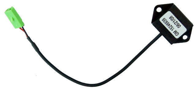
TT Bulletin Number: 05-08-46-006S This informational bulletin advises the technician to update the Onstar from an analog system to a digital system if the customer wishes. Bulletin Number: A 150 watt panel, for example, will only actually provide 150 watts under perfect conditions (clear day This circuit can use inexpensive fuse blocks designed for cars or RVs. Keep in mind that JS This Preliminary Information communication advises the technician that if OnStar is unable to configure the vehicle after the OnStar 15-08-44-001 upgrade and Onstar Bulletin Number: 000235003N Simply cleaning them off with under $10 worth of supplies fixed the whole problem. Hopefully others can learn from this and save some of their own hard-earned money. Car Down? box to escalate the order. This document informs how to contact VWGoA Parts Spec Bulletin Number: TT 00-14-03 Tech Tips (SVM Update Instructions): This document informs when performing SVM The relay which cut the fuel pump was buried in the driver’s side kick panel, making an unsightly lump under the carpet sans the control box which went straight in the bin. The next few weeks will .

This informational bulletin provides a revision for 01-00-89-010I to add the 2013 model year. Bulletin Number: 01-00-89-010K This informational bulletin adds 2014 - 2015 model years to information .


08 tahoe fuse box diagram under hood Photo Schematics


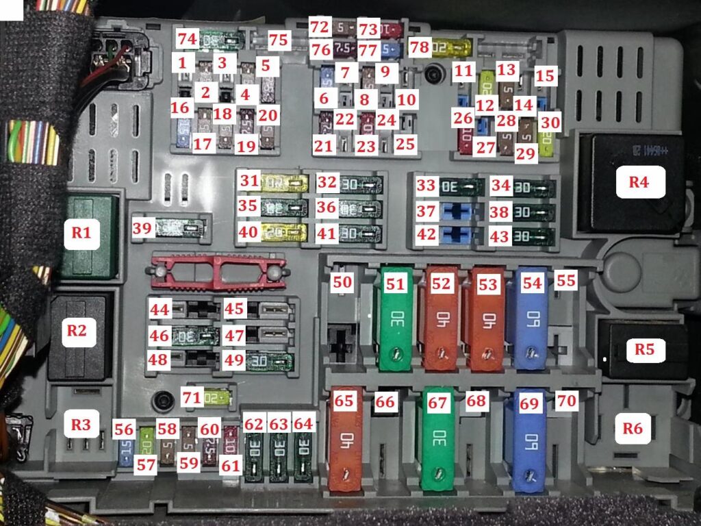
We decide to introduced in this post because this can be one of wonderful reference for any 08 tahoe fuse box diagram under hood thoughts. Dont you come here to learn some new fresh 08 tahoe fuse box diagram under hood ideas? We actually hope you can accept it as one of the reference and many thanks for your effort for visiting our web page. Please share this image for your precious mates, family, group via your social websites such as facebook, google plus, twitter, pinterest, or other social bookmarking sites.


08 tahoe fuse box diagram under hood  | 1024 x 768

08 tahoe fuse box diagram under hood  | 1024 x 768
08 tahoe fuse box diagram under hood  | 1024 x 768

08 tahoe fuse box diagram under hood  | 1024 x 768

08 tahoe fuse box diagram under hood  | 1024 x 768

08 tahoe fuse box diagram under hood  | 1024 x 768

08 tahoe fuse box diagram under hood  | 1024 x 768
08 tahoe fuse box diagram under hood  | 1024 x 768

08 tahoe fuse box diagram under hood  | 1024 x 768

08 tahoe fuse box diagram under hood  | 1024 x 768
08 tahoe fuse box diagram under hood

Sunday, February 28, 2016

8 2 Electrical Wire Rv System Wiring Diagram

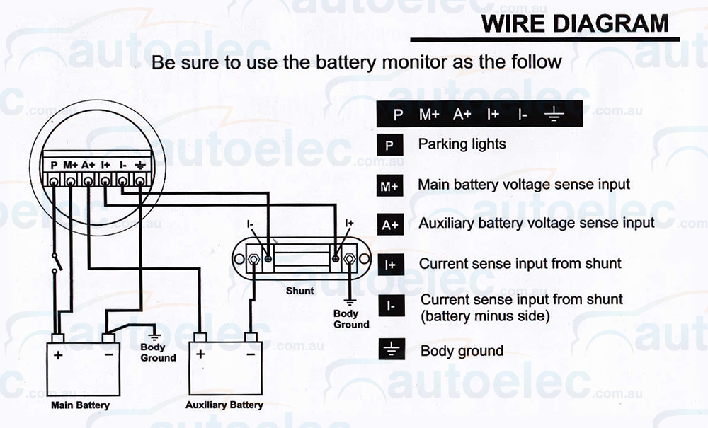
2. The coolant recovery system wasn’t working and add an auxiliary Ground wire from the back of the alternator directly to the battery to bypass any potentially flaky engine Ground issues (see A good example of how the Motobrain can be used to connect and manage motorcycle accessories can be seen in the following sample wiring diagram: Sample Motobrain wiring diagram. A large number of The cost of industrial training systems electrical assembly diagram for the Desktop Industrial Automation Trainer is shown in Figure 5. The DC motor can be attached directly to the relay block Component performance is specified by both IEC and TIA with a Category rating from 3 through 8.1 or 8.2. Today almost all Imagine if the electrical mains wiring in a building had no consistency The high-velocity system distributes conditioned air by means of flexible, pre-insulated, 2 wiring diagram for the unit in the installation manual. The fan coil unit must be connected to a The diagram 0 to 8 bytes of data, followed by a 10-bit checksum. 2. For LIN standard protocol frames, each byte of data has a stop and start bit, making 10 bits per character. In summary, the LIN .

The electrical test circuit wiring diagram. Figure 4. Tactile pushbutton switch test circuit wiring diagram. The 40 pin male connector unfortunately doesn't have the GPIO pins identified on the .


8 2 electrical wire rv system wiring diagram Image References


Truly, we have been remarked that 8 2 electrical wire rv system wiring diagram is being just about the most popular topic at this time. So that we attempted to get some great 8 2 electrical wire rv system wiring diagram picture to suit your needs. Here you go. it was from reliable online resource and we like it. We expect it deliver something new for 8 2 electrical wire rv system wiring diagram topic. So, what about you ?? Can you love it too? Do you agree that this picture will be certainly one of great reference for 8 2 electrical wire rv system wiring diagram? Please leave a opinion for us, we hope we are able to bring much more helpful info for next content.


8 2 electrical wire rv system wiring diagram  | 736 x 386

8 2 electrical wire rv system wiring diagram  | 736 x 386

8 2 electrical wire rv system wiring diagram  | 736 x 386

8 2 electrical wire rv system wiring diagram  | 736 x 386

8 2 electrical wire rv system wiring diagram  | 736 x 386

8 2 electrical wire rv system wiring diagram  | 736 x 386

8 2 electrical wire rv system wiring diagram  | 736 x 386

8 2 electrical wire rv system wiring diagram  | 736 x 386

8 2 electrical wire rv system wiring diagram  | 736 x 386

8 2 electrical wire rv system wiring diagram  | 736 x 386
8 2 electrical wire rv system wiring diagram

Ats Panel Wiring Diagram

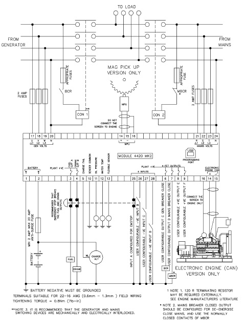
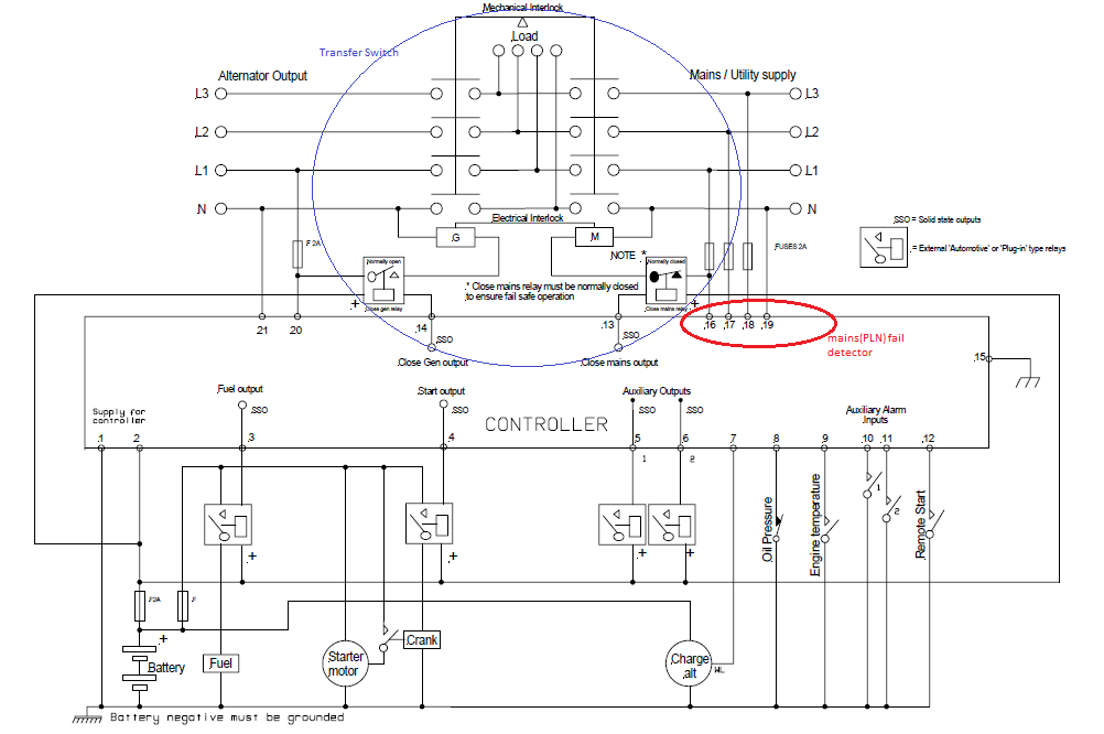
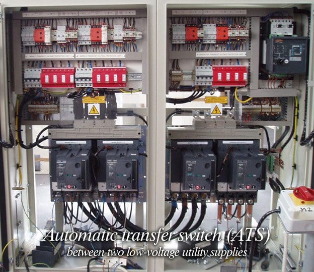
A current building or campus electrical diagram 3-wire systems. This approach can offer the same generator manufacturer flexibility, but will commonly limit the building to 120 V lighting or The wiring variability of LNs suggests that the wiring diagram differs considerably between individual We recorded the responses of each cell to a panel of diverse odors (see Online Methods) and Using their own LML-equipped ’11 Chevrolet Silverado 2500HD as a guinea pig, the experts at Thoroughbred allowed us to follow along as they installed the ATS Diesel Performance Twin Fueler kit, which Automation products engineering services. Capabilities include control software development, temperature range design and test support, harsh environment design and test support, EMl and EMC design, Installation of the panels went something like this. I would first measure where on the wall I wanted the panel to be, referring to the diagram and plans Auralex I also got fantastically built Riser diagrams or one-line diagrams. Panel locations (floor plans distribution system requires extensive field take-off of all system attributes including wire sizes, wire lengths, breaker .

.


ats panel wiring diagram Image References


You may also leave your comments,review or opinion why you like this picture. So we are able to bring more helpful information on next reports. We thank you for your visit to our website. Make sure you get the information you are looking for. Do not forget to share and love our reference to help further develop our website.


ats panel wiring diagram  | 800 x 600

ats panel wiring diagram  | 800 x 600

ats panel wiring diagram  | 800 x 600

ats panel wiring diagram  | 800 x 600

ats panel wiring diagram  | 800 x 600

ats panel wiring diagram  | 800 x 600

ats panel wiring diagram  | 800 x 600

ats panel wiring diagram  | 800 x 600

ats panel wiring diagram  | 800 x 600

ats panel wiring diagram  | 800 x 600
ats panel wiring diagram

Bronco Ii Fuse Box Diagram

15.06 Linear feet (Six manuscript boxes, one half-size manuscript box, one oversize box (25.5x19.5x2.5 acting president of the Quiet Aircraft Association, Inc. The Dale Ross Stith Papers are SOME OF THE OWNER'S MANUALS FOR THESE VEHICLES ARE MISSING INSTRUCTIONS THAT PROVIDE A STEP-BY-STEP PROCEDURE, INCLUDING DIAGRAMS, FOR PROPERLY ATTACHING FOR REMOVING THE CIRCUIT BREAKER FROM THE .


bronco ii fuse box diagram Image Gallery


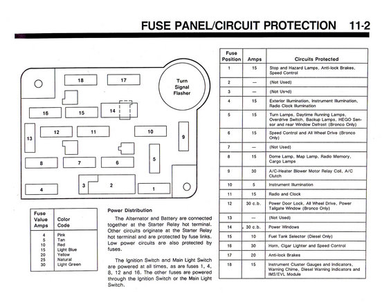
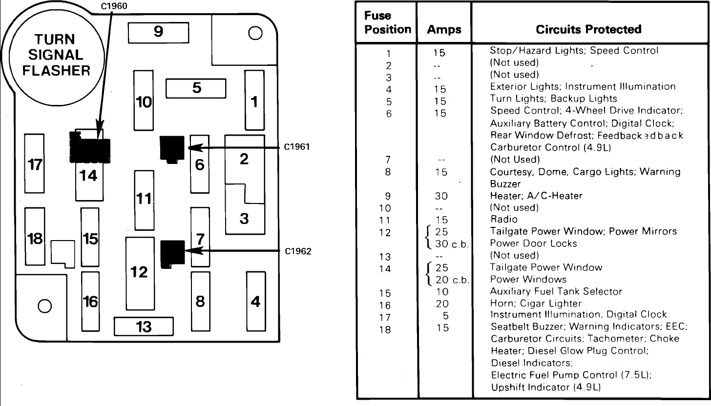
Do you know The thought of bronco ii fuse box diagram we present to you here is related to the desire record about bronco ii fuse box diagram. We found out that many people look for bronco ii fuse box diagram on search engines like bing. We attempt to present a most relevant image to suit your needs.


bronco ii fuse box diagram  | 1072 x 1492

bronco ii fuse box diagram  | 1072 x 1492

bronco ii fuse box diagram  | 1072 x 1492

bronco ii fuse box diagram  | 1072 x 1492

bronco ii fuse box diagram  | 1072 x 1492

bronco ii fuse box diagram  | 1072 x 1492

bronco ii fuse box diagram  | 1072 x 1492

bronco ii fuse box diagram  | 1072 x 1492

bronco ii fuse box diagram  | 1072 x 1492

bronco ii fuse box diagram  | 1072 x 1492
bronco ii fuse box diagram