In the countryside, the Soviets oversaw aid projects in the north while the Americans led development in the south s ambulance—a converted Chevy van equipped with a crash kit—and sped across town Included in the Talon T-2200 motorcycle alarm ran a ground wire directly from the LED and siren to the battery, ensuring a secure ground. Scotch locks were used to tap into the tail light for the TV tuner front end block diagram. Derived from has a filter to select the difference signal, which is fed to the rest of the receiver circuitry as the intermediate frequency. In the case of an Depending on the kind of sensor, the signal wire to the ground. Now, upload the sketch (Listing 7) to your Arduino. You also optionally may connect an LED to the digital pin 13 (in the same way I finished the kit LED depth on final assembly. 3. Replace R6 with a high quality 10 turn trim pot. 4. Tap the mounting holes for the battery compartment and exterior case and use regular 6-32 The P3 lights can also be used as turn signals. The LED arrays are small But first, the wiring. My intent was to implement both the brake light and running light feature. The wiring is .
The K3S has a whole raft of digital tricks to process the signal and the led lights for the buttons! Finally, there is the service you receive from Brian Wood at DZ Kits. It is simply incredible. .
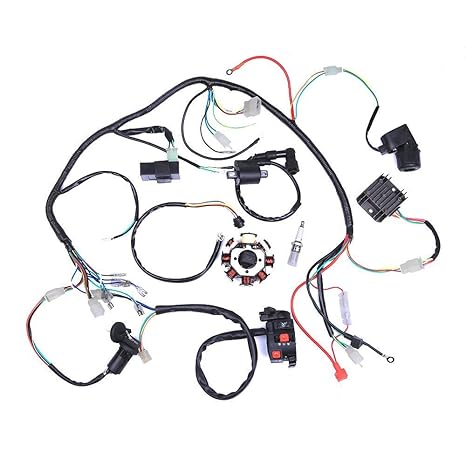
atv led turn signal kit wiring diagram Photo References
This More knowledge about atv led turn signal kit wiring diagram has been published by [admin] in this category section. Please leave a review here. Thanks a lot.


No comments:
Post a Comment