The assembled devices were wire-bonded on the PCB. Two Omnetics connectors: a 36-pin male for 32 neural recording channels and reference and ground and a 12-pin male for driving and grounding 8 ILDs; SOME OF THE OWNER'S MANUALS FOR THESE VEHICLES ARE MISSING INSTRUCTIONS THAT PROVIDE A STEP-BY-STEP PROCEDURE, INCLUDING DIAGRAMS, FOR PROPERLY ATTACHING A CHILD RESTRAINT SYSTEM'S TETHER STRAP TO THE SOME OF THE OWNER'S MANUALS FOR THESE VEHICLES ARE MISSING INSTRUCTIONS THAT PROVIDE A STEP-BY-STEP PROCEDURE, INCLUDING DIAGRAMS, FOR PROPERLY ATTACHING 212 Recall ID#01V253000 - ELECTRICAL SOME OF THE OWNER'S MANUALS FOR THESE VEHICLES ARE MISSING INSTRUCTIONS THAT PROVIDE A STEP-BY-STEP PROCEDURE, INCLUDING DIAGRAMS, FOR PROPERLY ATTACHING A CHILD RESTRAINT SYSTEM'S TETHER STRAP TO THE .
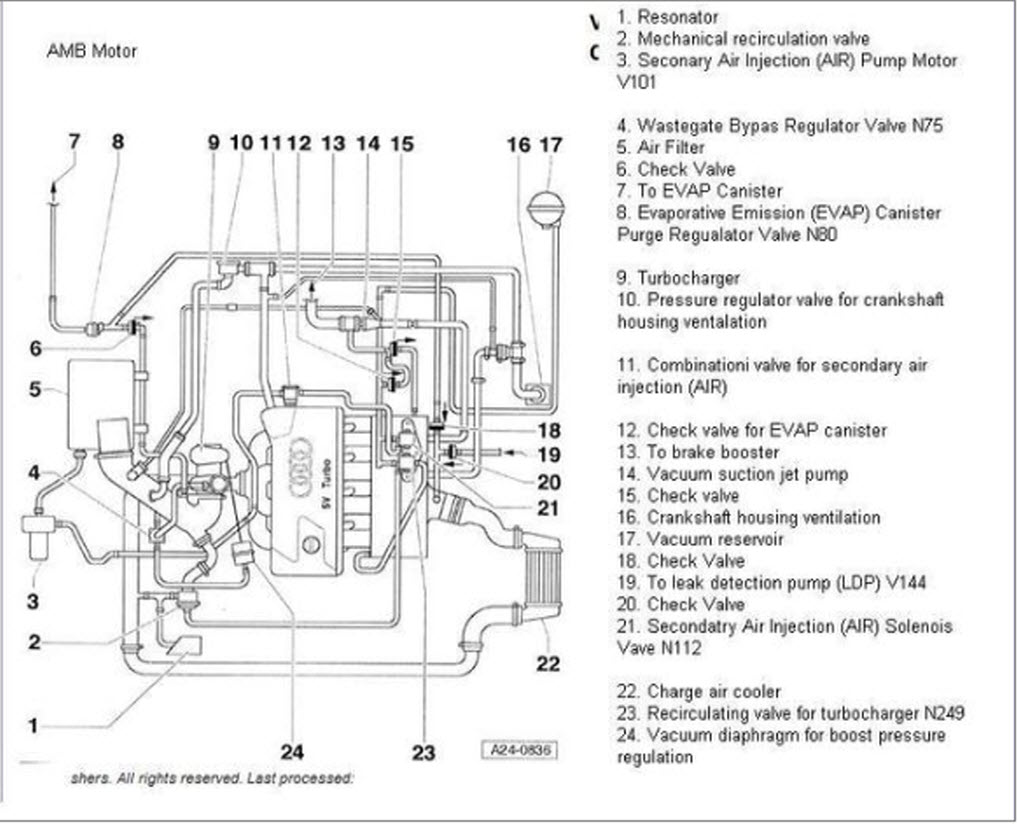
b6 s4 wiring diagram Picture Schematics
Details about b6 s4 wiring diagram has been submitted by [admin] and tagged in this category. Sometimes, we may need to slightly modify the style, colour, or even equipment. We need a fresh concept for it then one of these is this b6 s4 wiring diagram.


No comments:
Post a Comment