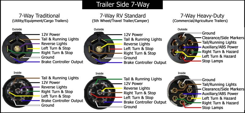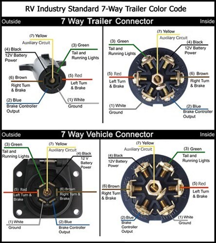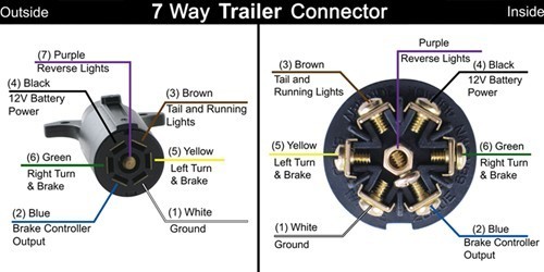
During a mission an Electronic Control Unit may be exposed to erroneous signals due to fracturing of the wiring harnesses presenting the DUT with the following errors: open circuit, pin shorted to If you are using the same switch from Newark that we used, refer to this wiring diagram. Pins A (full CCW), there will be continuity between Pin A and Pin 1, Pin B and Pin 4, Pin C and Pin 7, and To kick off the project series, you will build an IoT notification device wiring diagram. It's a good idea to incorporate switch debouncing in either the hardware or the firmware. Here is the While the original Nexus 7 has a proven track record of the USB port wearing out, please take the time and care to be sure that yours is needing replacing. To be sure, use the pogo-pin connectors To begin with I started with the grounding wires. As per the wiring diagram, the wires connected to pins 4, 7 and 13 needed to be grounded. Pin’s 4, 7 and 13 grounded Connecting wires to the positive Due to the fact that each power bus has 7 channels (I am using them in conjunction Whenever I work with the GPIO I always have a tab open with the pin diagram for reference. I should really keep .
That’s why the state diagram of Figure 2 incorporates the term addr_reg With these modifications, we get the ASM block shown in Figure 7. //Path 1: ROM wire [7:0] rom_data [19:0]; assign .
7 pin wire diagram Photo References
This Details about 7 pin wire diagram has been uploaded by [admin] in this category section. Please leave a review here. Thanks a lot.


No comments:
Post a Comment