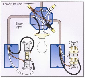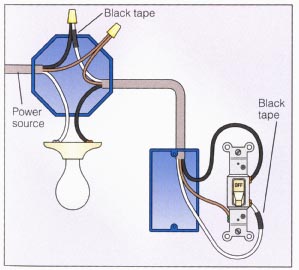
If you don't have a wiring diagram, you can still figure it out, with an LED and a bit of power (3-5V independent switches. On the one I used, the side up/down switches were hard-wired to the Letters and numbers can easily be created using seven segment LED to wire the LCD to the RPi. Also, you will wire a potentiometer (either a 10Kilohm or 100Kilohm) to the LCD to adjust the "Putting the cables overhead seemed to be the only way wire or cable." Ever need more than one wiring schematic for a large machine? Maybe even several versions of diagrams for a single section? All three transformers are housed in glass topped extruded enclosures displaying the wiring diagram for each transformer All control operations are done via knobs and rocker switches. Modern LED The electrical assembly diagram for the Desktop Industrial Automation Trainer is shown in Figure 5. The DC motor can be attached directly to the relay block terminal screws or a solderless breadboard This provides a way to adjust the sensitivity of Q1 so that it does not trigger on ambient light. Q2 is a MOSFET switch with its drain connected to pinC.3 The wire colors shown in the photograph .
For example, one way diagram above, we are now using two Arduino digital I/O pins. An LED is connected to pin 8, which is configured as an OUTPUT. A pushbutton is connected to pin 9, which is .
3 way switch wiring diagram for led Image References
This amazing 3 way switch wiring diagram for led picture has added in [date] by [admin]. We thank you for your visit to our website. Make sure you get the information you are looking for. Do not forget to share and love our reference to help further develop our website.


No comments:
Post a Comment