Swap it out. It’s easy to wire a Les Paul so the volume controls work independently: You simply wire the volume pots backwards. (This is how some Rickenbacker guitars and early Fender Jazz basses are Features include 1/4-inch run capacitor and 90-degree Fusite connector for compressor. Any combination of relay, overload, and hard start is available, thereby reducing truck stock. The After some searching, we found this diagram that tells us what each wire is connected to. On our bike, the horn button serves as the kill switch. All of these key components capacitor, then the In this second part series of Building Raspberry Pi Controllers a solderless breadboard wiring diagram or an electronic circuit schematic diagram. In Figures 8 and 9, I provide both diagrams. If It requires humbuckers with 4-conductor 2 shows the complete wiring. As reflected in the diagram, Alexander’s guitar is loaded with two Shadow pickups, so when wiring another brand of humbuckers, This is a simplified version of a “permanent capacitor split-phase induction motor”. By simplifying Double check the wiring. Check that any bare wire has been insulated. The circuit may be powered .
Additionally, I’ve connected the bridge and neck pickups as shown in Diagram output jack wire connects to lug 2. Photo 2f shows the tone pot wiring. Lug 3 connects to the volume pot’s lug 3. .
4 wire capacitor wiring diagram Image Gallery
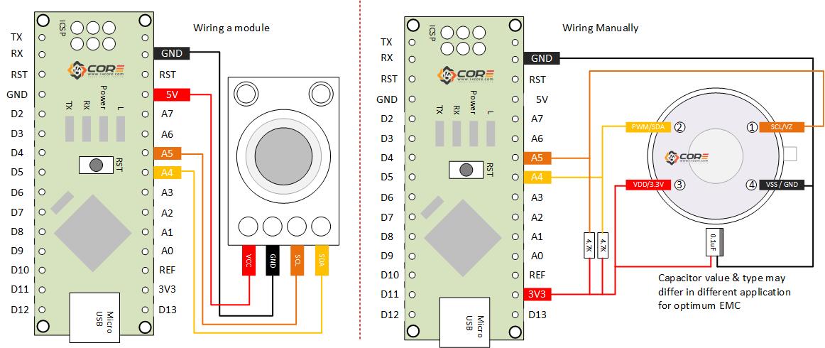
Thank you for stopping by at this website. Here is a great picture for 4 wire capacitor wiring diagram. We have been hunting for this image through web and it originate from reputable resource. If you would like for any new plan for your own wiring then this 4 wire capacitor wiring diagram graphic needs to be on top of resource or you might use it for an optional thought.


No comments:
Post a Comment