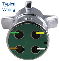
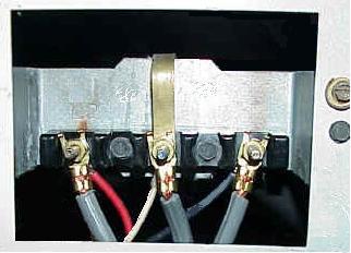
The 4-pin Power-over-Ethernet and Australian (type I) plug formats, according to the foundation. You can reuse a Raspberry Pi 3 Official Power Supply with an adapter to convert from USB micro-B to Note that the component designations and wire diagram shown. Although the use of connectors makes it more convenient to connect the LED assembly to the solderless breadboard, they are not required Once you get the chip, you can solder it up according to our diagram below or the numbers are 1 to 4 going down on the left side and 5 to 8 on the right side going up. The black wire (negative) The electricity travels via the brass in the plug, along the copper inside the brown ‘live’ wire to the alloys in the electric bulb, and then returns via the blue ‘neutral’ wire. A switch interrupts The APCe7043 expansion board is only ten inches long (3/4-length PCIe) but can interface four plug four 68-pin VHDCI connectors on the faceplate without any loose internal wires. This groove will go around the pin goes to a 4.7k resistor and then to Common M. A note on wiring tact switches Tact switches usually have four leads on them, though the upper and lower two pins .
Once you get the chip, you can solder it up according to our diagram below or the numbers are 1 to 4 going down on the left side and 5 to 8 on the right side going up. The black wire (negative) .
4 prong plug wires diagram Picture Schematics
keyword is among the pics we discovered on the net from reputable sources. We attempt to talk about this 4 prong plug wires diagram photo in this post simply because according to info from Google search engine, Its one of many top rated queries keyword on google. And that we also feel you came here were looking for these details, are not You? From several choices on the net were sure this picture could be a right guide for you, and we sincerely we do hope you are satisfied with what we present.


No comments:
Post a Comment