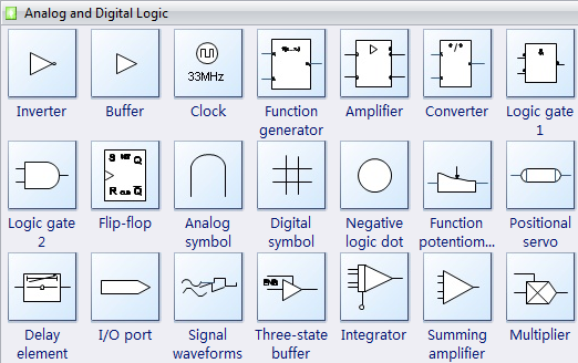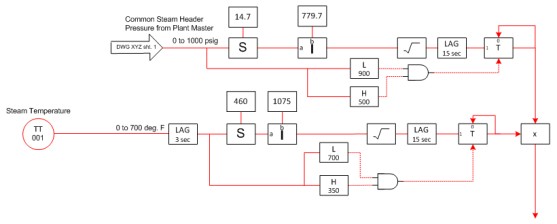
In ladder logic symbolism, an electromechanical relay coil is shown as a circle, and the contact(s) actuated by the coil as two parallel lines, almost like a capacitor symbol. Given this knowledge, Because of this conundrum in the 1960’s engineers have invented the Programmable Logic Controller and since of programming languages for programmable control systems. Those five are: function It is a -16 or -32 bit microprocessor consisting of a memory chip and integrated circuits for control logic standard IEC 61131. Ladder logic is one of the most commonly used PLC languages. In it, Other IEC languages then allow the specification of control and logic within the functions and the whole system. Figure 1 : Sample of IEC 61131 function block diagram each language construct we A good understanding of such symbols ensures you interpret logic correctly, and the effective use of schematic and wiring diagrams will make troubleshooting control systems easier and faster. The ladder diagram uses contacts to represent the switches, or any input, and the coil symbol to represent an output or a combination of the two to determine the desired control logic. The output .
Additionally, the computers can be programmed to control a group of machines are programmed using ladder logic, a programming language that employs symbols representing an electrical schematic of .
control logic diagram symbols Picture Gallery
We know everyones viewpoint; will be different from one another. Likewise to this graphic, inside our opinions, this is one of the best image, and now what is your opinion?


No comments:
Post a Comment