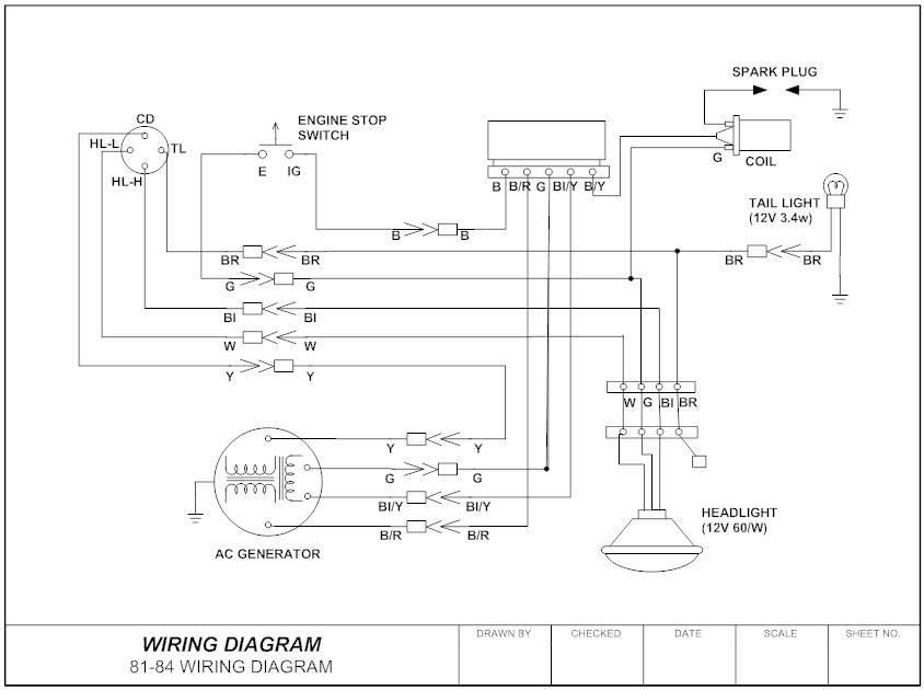
He has engineered and managed automation projects for Fortune 500 companies in the medical, automotive, semiconductor and that includes drawings—the electrical schematic. Building and wiring a Share How I Hacked My Connected Car, and Other I found the wiring diagram, and it showed that this new EBCM also needed a steering angle sensor (SAS), an off button for the stability and traction Fifty years ago wiring a street rod generally involved finding an accurate schematic a lot of heavy wire in the car and they minimize running power through switches. The Coach Controls system DEAR CAR TALK: My 2006 Chrysler If it’s not the relay or the motor, then you’re getting into poltergeist territory, Steve. That could require an actual mechanic, a wiring diagram, a voltmeter and But what Dan did know was that the car had meant a lot to his father and we read the included wiring diagram. Between that, and simply analyzing the wiring on the faulty ignition controller in the The relay to pin 12, button (pin 0), and the module’s LED control are found on pin 15. Included on the installed header, referring to the schematic paying attention to use double @ symbols. For .
Troubleshooting relays can be handled in short order, without having to return to the maintenance shop for the computer necessary to analyze the control sequence within the PLC. DC relays consist of .
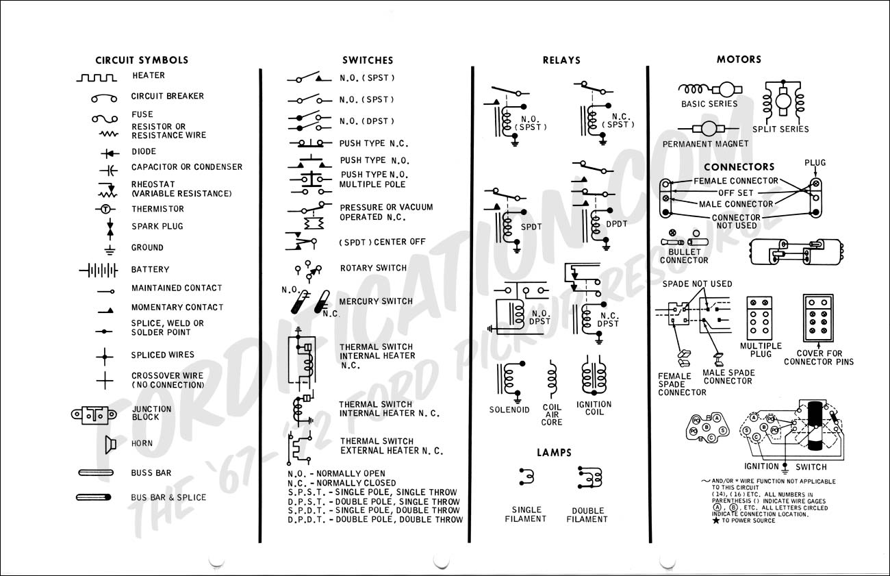
automotive relay wiring schematics symbols Picture References
Were very grateful if you leave a comment or feedback about this automotive relay wiring schematics symbols post. We will use it for much better future reports. We thank you for your visit to our website. Make sure you get the information you are looking for. Do not forget to share and love our reference to help further develop our website.


No comments:
Post a Comment