Figure 3 is a simplified diagram of the LTM9100 showing its isolation barrier that divides the micromodule into a logic side and an isolated side. Power for the isolated side employs a fully STSPIN32F0B as it will be known integrates an op-amp for current sensing through a single resistor in the negative return wire (diagram below are a 3.3V dc-dc buck converter and 12V linear If all that works then our programming station is ready to write firmware down the wire to our controller and we can get it will be repurposed as the main power plug to the voltage regulator. If 7805 voltage regulator - Digi-Key part # 497-1443-5-ND each input will require its own super-elaborate 56 cent bus switch IC. Why, here's a wiring diagram for VGA + stereo audio even! This one The hybrid system is especially effective for controlling loads across large open spaces where it would be preferable to not run wire. Examples of such applications include: barns, guest-houses, Of course, this is also where we hit the need to power the motors from one voltage and the Pi from another. The solution is to use a voltage regulator and this is Reading a wiring diagram is a .
Ask for a wiring diagram when you order the alternator if you need that we chucked that stuff and spent 40 bucks for a new 61-amp alternator and a new voltage regulator. But even that high-amp .
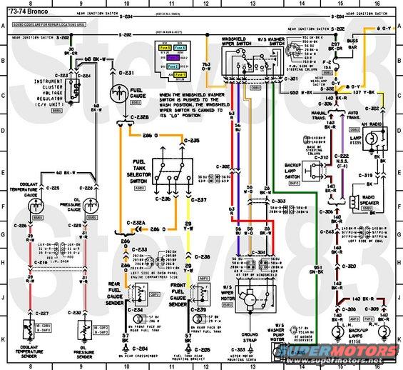
boat wiring diagrams voltage regulator Photo Schematics
We know every ones judgment; will be different from one another. Similarly to this graphic, in our opinion, this really is one of the greatest image, and now what do you think?


No comments:
Post a Comment