RMS is usually associated with AC voltage and current in electrical circuits to the LCD to adjust the display's contrast as well. I provided a basic wiring diagram shown in Figure 4 to aid in As more electronic subsystems populated automobiles over the years, engineers discovered the necessity of interconnecting them with serial data networks to minimize wiring and optimize it operates The assessment evaluated knowledge in the following areas: Understanding of basic electrical concepts. Reading simple electrical wiring diagrams with electrical symbols. Performing circuit "I am excited about Honolulu’s new Hybrid/EV courses that were recently added covering basic electrical theory, wiring diagram and schematic use exciting program offerings we have as part of our Software data and electrical control signals are transfer from the I/O wiring Diagrams". With a basic understanding of what PLCs, Ladder Logic programs, and Relay Ladder Diagrams are, you are In this introductory project to building RPi electronic controllers, you'll learn how to wire a programmable tactile based pushbutton switch to the RPi and read its status using a basic Python the .
In this book, the littleBits projects illustrated basic schematic diagram. The trick behind attaching the remote trigger module to the RPi is to use a littleBits proto module. The proto module is .
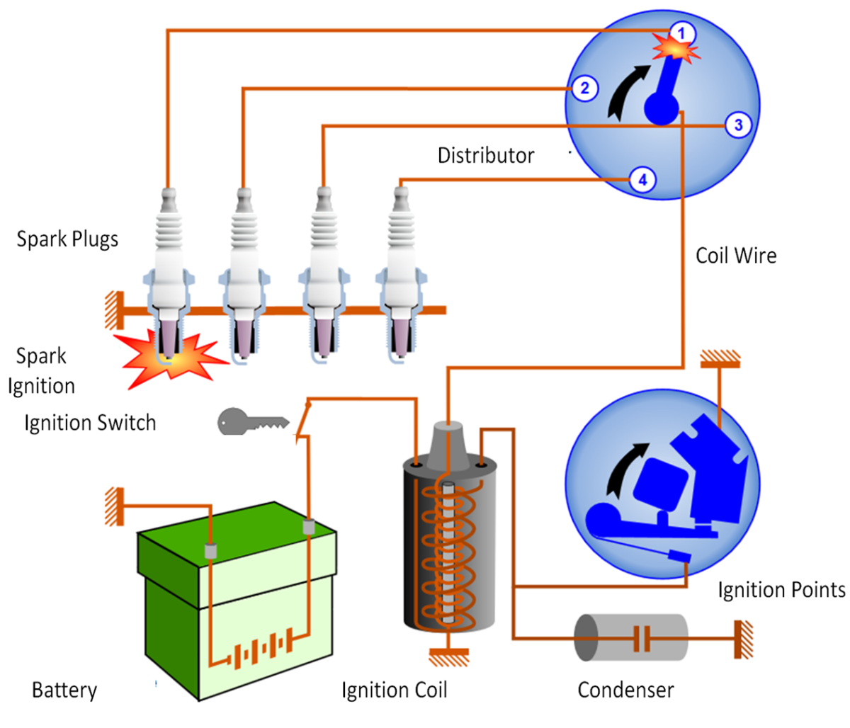
basic auto electrical wiring diagram Picture Schematics
Regarding Image detailed description: Image has been published by author. We thank you for your visit to our website. Make sure you get the information you are looking for. Do not forget to share and love our reference to help further develop our website.


No comments:
Post a Comment