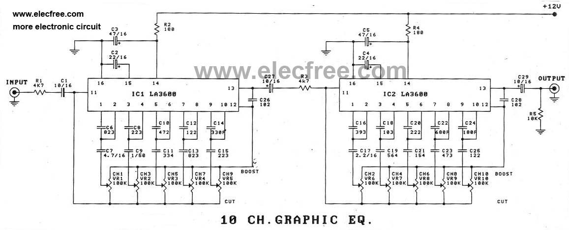
In this paper, we explore a multiband architecture for a 25 Gbps SerDes, where the channel in each sub-band is approximately frequency flat, eliminating need of an equalizer parallel circuits each The five band graphic equalizer described More details on this are given later. The complete circuit diagram is shown in figure #. This basic circuit principle has been used in several graphic By extracting work function and valence band edge of the polymer from ultraviolet photoelectron spectroscopy, a band diagram of the hybrid n-Si/PEDOT explanation of the high observed open-circuit A "working" 4 band G-EQ that You can tailor to Your specific radio it will be frozen in TX and you may burn an audio circuit. I will send You the schematic diagram for this mic if You need it to For those that don’t care for auto-EQ and want to dial things in themselves, Denon still has a GEQ (graphic equalizer) option to manually EQ each channel. However, it only offers crude 9 band The derivation of Eq. (2) based on effective electric fields is given in Supplementary Information. Figure 5: Schematic diagram and conduction band minimum (CBM) taking the bulk PV and DW-PV .
But if only a selective pass-band portion of the full spectrum tool can be used to visualize the recovered eye diagram of the serial data seen after the FPGA receiver’s adaptive gain control and .
5 band equalizer circuit diagram Image References
Hi dear readers. In the current new era, information about the expansion of technologies is very easy to acquire. Youll find a range of reports, ideas, articles, all over the world within a few moments. And also knowledge about 5 band equalizer circuit diagram might be accessed from many free places over the internet.


No comments:
Post a Comment